What Is an OTDR?
An OTDR is a fiber optic tester for the characterization of optical networks that support telecommunications. The purpose of an OTDR is to detect, locate, and measure elements at any location on a fiber optic link. An OTDR needs access to only one end of the link and acts like a one-dimensional radar system. By providing pictorial trace signatures of the fibers under test, it’s possible to get a graphical representation of the entire fiber optic link.
What an OTDR Measures?
Injecting pulses of light into one end of a fiber and analyzing the backscattered and reflected signals, an OTDR measures:
Optical Distance
- To elements: splices, connectors, splitters, multiplexers …
- To faults
- To end of fiber Loss
Optical Return Loss (ORL)/Reflectance
- Loss of splices and connectors
- ORL of link or section
- Reflectance of connectors
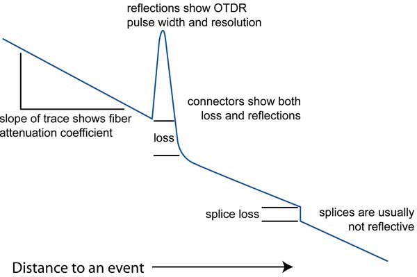
- Total fiber attenuation
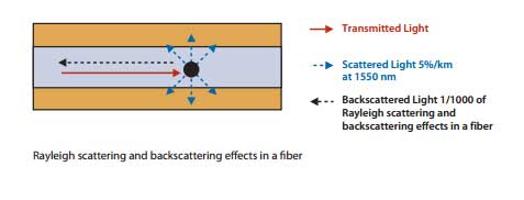
Logically specking, the OTDR will use two different methods to perform these tests. Rayleigh Scattering is the first method. When the OTDR pulses light down the fiber, the light will collide with particles that are in the fiber. When the light hits these impurities, the light will be scattered in every direction. Some of this scattered light (typically around 0.0001%) is shot down the glass in the opposite direction back to the OTDR. Rayleigh Scattering occurs along the entire length of the fiber and it a huge loss factor in fiber.
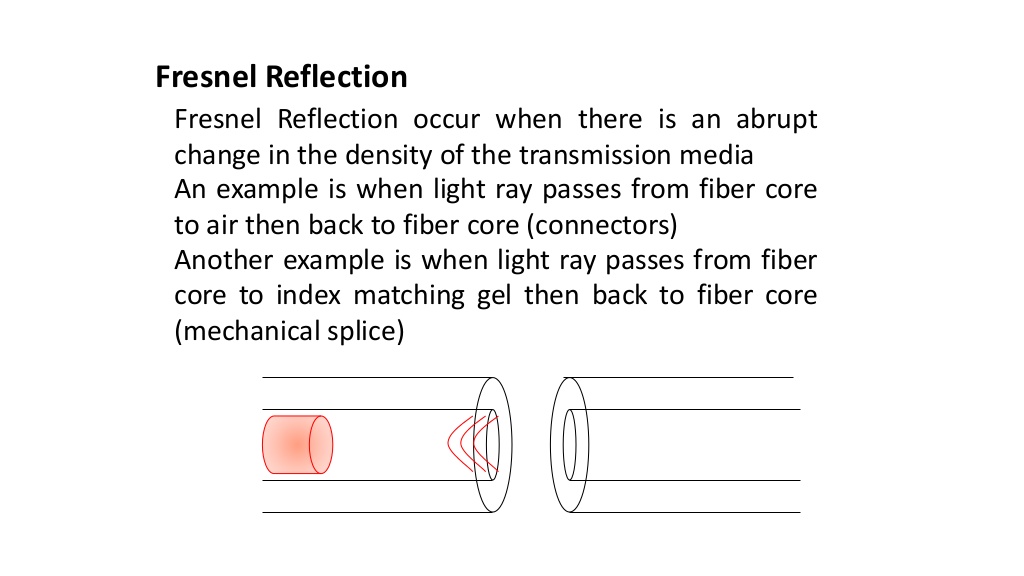
The second method the OTDR will use is called Fresnel Reflections. These types of reflections occur when light traveling through the glass encounters a different density which will change the light speed. Some of the light (typically around 4%) is reflected back to the light source. Fresnel Reflections can have power up to 40,000 times as much as backscatter. Fresnel reflections will be shown on your OTDR at connector points as well as mechanical splices that were put in the line.
The typical reflectance for some common applications can be seen below. This is what you can expect to see as a loss on your OTDR when you encounter these characteristics of your fiber.
- Fiber end with flat cleave: -14 dB
- Good multi-mode PC connection: -35 dB or lower
- Good single mode PC connection: -50 dB or lower
- Good angle-polish connection: -60 dB or lower
- Good fusion splice: -60 dB or lower
The two types of attenuation can basically be broken down into non reflective or reflective attenuation. We will briefly touch on the differences in these two below.
Non-Reflective Attenuation
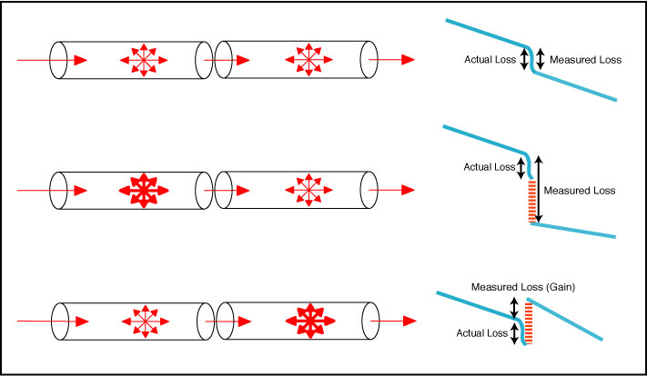
Sometimes when viewing the OTDR readout you will notice a sudden drop in the graph. This drop represents an event that causes attenuation. When there is attenuation and no previous spike, a non-reflective event is now identified. That attenuation with no reflection is typically indicative of a kink, bend or fusion splice somewhere in the fiber cable.
Reflective Attenuation
Reflective attenuation looks different on the OTDR than a non-reflective attenuation. The most distinct difference is that a reflective event shows a spike before the attenuation. This may be cause by a connector on the fiber or a mechanical splice that has been added to the fiber. The reflection is created when light passes between substances that have different indexed of reflection (glass to air). Reflective attenuation (same as Fresnel Reflection we reviewed on the prior page) occurs when light leaving the glass core of the fiber encounters an air gap within a fiber optic connector or when light travels from glass to index matching gel in a mechanical splice. The height of the spike represents the amount of power that is being wasted through reflection.
When using your OTDR you will come across Dead Zones in your tracing. Dead Zones refer to the amount of time (distance) that is lost on a fiber trace that follows a reflective attenuation. This trace section will be in correlation the portion of the fiber test that is closest to your OTDR unit. The Dead Zone part of a trace has no way to be reliably tested. This problem occurs on account of the sensor on the OTDR measuring backscatter levels in a fiber. Essentially, the OTDR becomes blinded when it encounters a much larger Fresnel Reflection. This blind period will last as long as you have the light pulse duration set for on the OTDR. When the light comes back to the OTDR as a high level of light, the OTDR becomes over saturated and can’t properly measure the lower levels of backscatter that follow this event.
Which one is a perfect OTDR?
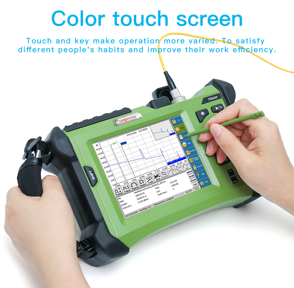
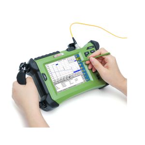
ORIENTEK TR600 OTDR with multi-functions this product is beloved by many customers. Since its event dead zone is less than 1.8m, when processing, it can test and make the analysis in short speed. According to the different requirements, it can be placed anywhere with easy to store and measure data function, if there is any need, it can be connected to the personal computer for the further data analysis. Meanwhile, people can use it for fast detection of conducting breakpoints with constant brightness and flicker mode under the VFL detection. With this device, anything can be automatically detected of input laser signals.
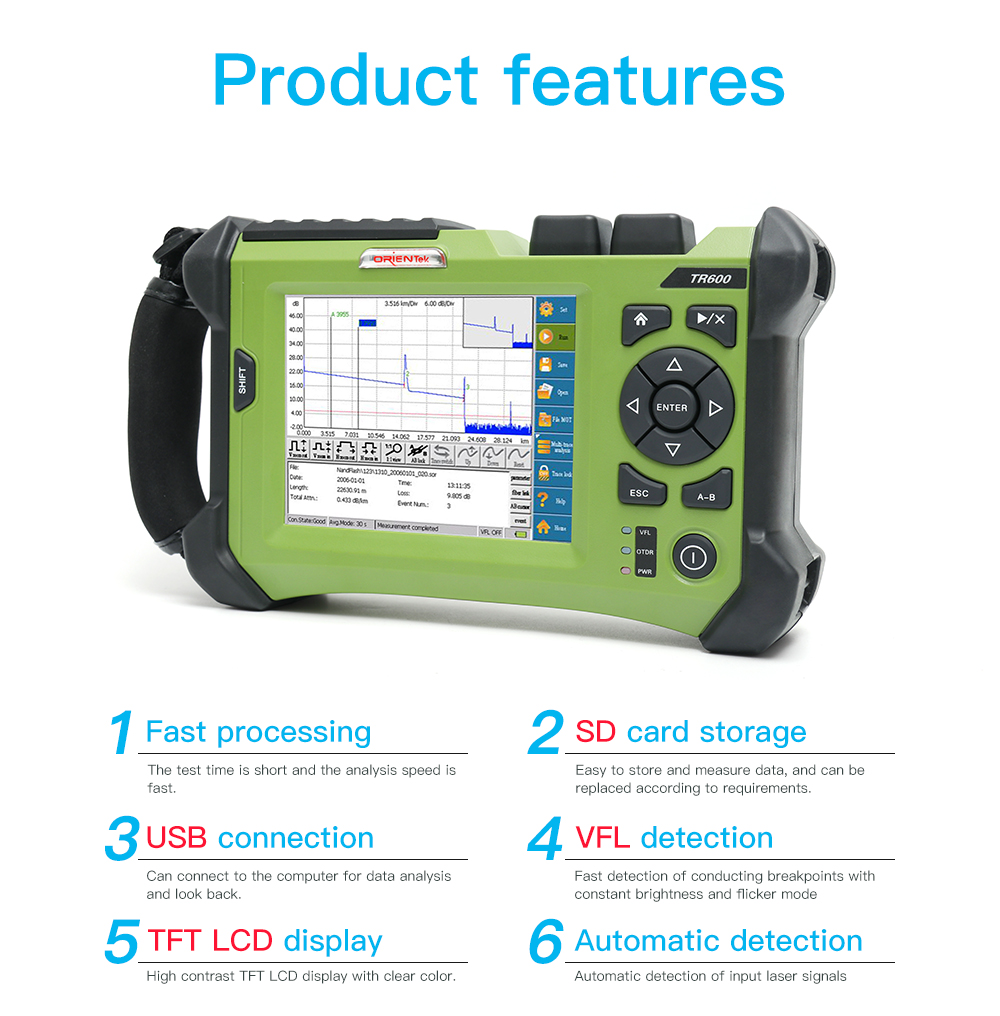
GUI Interface design helps the operation become more simple and people can witness intuitive reflection of the measurement data.