1. Use of OTDR
Fiber optic measurements with OTDR can be divided into three steps: parameter setting, data acquisition, and curve analysis.
Manually setting measurement parameters includes:
(1) Wavelength selection (λ):
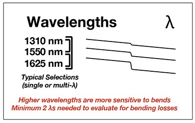
Because different wavelengths correspond to different light characteristics (including attenuation, microbend, etc.), the test wavelength generally follows the principle corresponding to the transmission wavelength of the system transmission, that is, when the system is open at 1550 wavelength, the test wavelength is 1550 nm.
(2) Pulse Width:

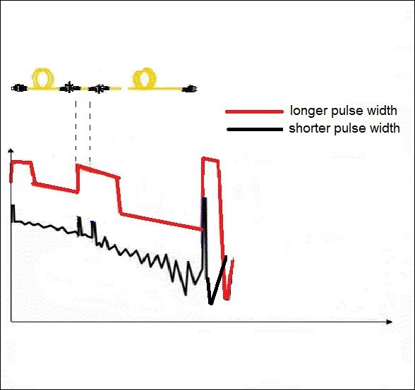
The longer the pulse width, the larger the dynamic measurement range and the longer the measurement distance, but the blind zone is larger in the OTDR curve waveform; the short pulse injection light is lower, but the blind zone can be reduced. The pulse width period is usually expressed in ns.
(3) Measurement range:
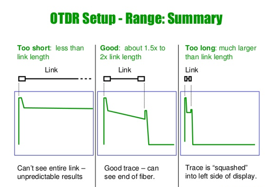
The OTDR measurement range refers to the maximum distance that the OTDR acquires data samples. The choice of this parameter determines the size of the sampling resolution. The optimal measurement range is between 1.5 and 2 times the length of the fiber to be tested.
(4) Average time:
Since the backscattered light signal is extremely weak, a statistical average method is generally used to improve the signal-to-noise ratio, and the longer the average time, the higher the signal-to-noise ratio. For example, a 3 min acquisition would take a 0.8 dB improvement over the 1 min acquisition. However, the acquisition time over 10 minutes does not improve the signal-to-noise ratio. The average time is usually no more than 3 minutes.
(5) Fiber parameters:
The setting of the fiber parameters includes the setting of the refractive index n and the backscattering coefficient n and the backscattering coefficient η. The refractive index parameter is related to the distance measurement, and the backscattering coefficient affects the measurement of the reflection and return loss. These two parameters are usually given by the fiber manufacturer.
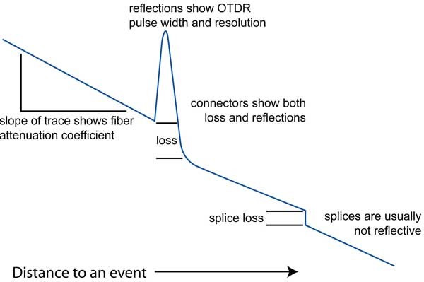
After the parameters are set, the OTDR can send optical pulses and receive the light scattered and reflected by the fiber link. The output of the photodetector is sampled to obtain the OTDR curve. The curve can be analyzed to understand the fiber quality.
2. Experience and skills
(1) Connector cleaning:
Before the optical fiber connector is connected to the OTDR, it must be carefully cleaned, including the OTDR output connector and the tested live connector. Otherwise, the insertion loss is too large, the measurement is unreliable, the curve is too noisy, and the measurement cannot be performed. It may also damage the OTDR.
(2) Correction of refractive index and scattering coefficient: For the measurement of fiber length, the deviation of refractive index per 0.01 will cause an error of 7m/km. For longer light segments, the refractive index provided by the cable manufacturer should be used. value.
(3) Identification and processing of ghosts:

The spikes on the OTDR curve are sometimes echoes due to strong reflections from the incident end, which are called ghosts. Identifying ghosts: The ghosts on the curve do not cause significant loss; the distance between the ghost and the beginning of the curve is a multiple of the distance between the strong reflection event and the starting point, forming a symmetry. Eliminate ghosting: Select a short pulse width and increase the attenuation at the strong reflection front end (such as the OTDR output). If the event that caused the ghost is at the end of the fiber, you can "small bend" to attenuate the light reflected back to the beginning.
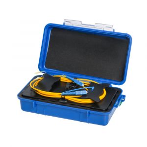
(4) Use of additional fiber:
In general, the connector between the OTDR and the fiber to be tested causes the largest dead zone. In the actual measurement of the optical fiber, a transitional fiber is added between the OTDR and the fiber to be tested, so that the blind spot of the front end falls within the transition fiber, and the beginning of the fiber to be tested falls in the linear stable region of the OTDR curve. Fiber optic system start connector insertion loss can be measured by OTDR plus a transition fiber. To measure the insertion loss of the connectors at the first and last ends, add a transition fiber at each end.