The basic principle of OTDR fiber tester is to measure the transmission loss caused by scattering, absorption, etc. and the structural loss caused by various structural defects by analyzing the backscattered light or forward scattered light in the fiber. When a certain point of the fiber is subjected to temperature or when the stress acts, the scattering characteristics of the point will change. Therefore, the disturbance information of the external signal distributed on the sensing fiber is detected by the correspondence between the display loss and the length of the fiber. How to read OTDR test curves?
Normal curve
Generally, it is a normal graph, A is a blind zone, and B is a test end reflection peak. The test curve is tilted, and as the distance increases, the total loss will increase. The total loss (dB) divided by the total distance (Km) is the average loss (dB/Km) of the core.
1. fiber has jumper point
There is a reflection peak in the middle because it is very likely that there is a jumper point in the middle. There are of course exceptions. In short, there are reflection peaks, many of which are due to the flat end of the fiber end. The flatter the end face, the higher the reflection peak. For example, in an interrupted cutover, when the cable is cut, the test curve should be as shown in the breakpoint of the light path, but when you test again, if there is a reflection peak at the original breakpoint, it means the repair of the scene. It is very likely that the person has already finished the end face of the core.
2. abnormal situation
In the case of the picture, it may be that the pigtail of the meter is not plugged in, or the light pulse cannot be played at all. Then the position of the breakpoint is relatively close, and the distance and pulse setting used are relatively large, which looks like the light didn't go out. In this case, one should check the connection of the pigtail fiber. The second is to change the setting of the OTDR and adjust the distance and pulse to the minimum.
3. non-reflective event
This kind of situation is more common, there is a significant step in the middle of the curve, most of which is the core is discounted, the bending is too small, and the external damage and other factors. This step in the curve is a relatively large loss point. It can also be called an event point. The curve falls down at this point. It is called a non-reflective event.
4. fiber breakpoint
This situation must be brought to the attention! The curve does not have any reflection peak at the end and falls. This means that the fiber is broken at the point where the curve falls, or it is possible It was the fiber that made a break there.
5. test distance is too long
This situation occurs when the long-distance core is tested, the OTDR cannot be hit by the distance, or the distance and pulse settings are too small.
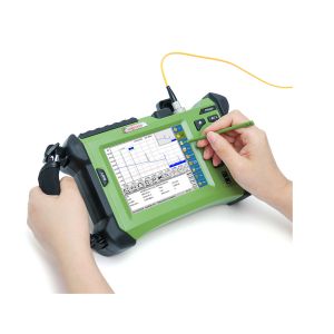
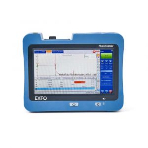
Knowing the common test curve of OTDR, let's share the mini ORIENTEK OTDR K330
ORIENTEK high precision OTDR K330 is a 1310nm&1550nm wavelength OTDR, 3.5in GUI interface; 1.6m dead zone; 10m ATT dead zone; 130km measure range; 15 hours of standby;10km VFL; up to 32dB dynamic range; over ten thousand storage capacity and so on.
OTDR mainly serves optical fiber communication, so the test wavelength should be selected first before optical fiber testing, and 1550nm should be selected as far as possible for single-mode optical fiber. Why? The reason is that the wavelength of 1550nm is more sensitive to the bending loss of optical fiber than that of 1310nm. Whether it is the construction of optical fiber line or the maintenance of optical fiber line, the wavelength of 1550nm is usually selected when testing the whole fiber back-scattering signal curve of a certain optical fiber transmission link by OTDR. Orientek has OTDR K330 which is only tested 1550nm wavelength.
This OTDR is small in size, and the fiber OTDR price is discounted. The OTDR specifications are detailed on our website.
Click here to lean more about this OTDR: